
Parallel Seiesmic
Paralleles Seismisches Instrument
Übersicht
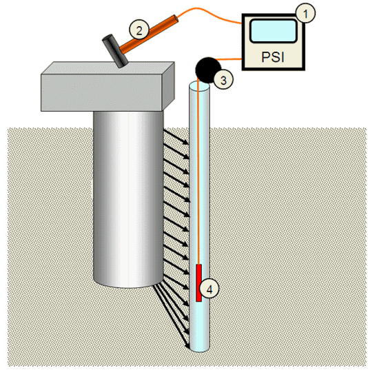
PSI verwendet die bekannte Parallel – Seismic - Methode, um die Tiefe bestehender Fundamente zu ermitteln (speziell für Pfahl- oder Pfahlgründungen), wenn der Überbau (d.h. das bestehende Gebäude) den Zugang zu den Pfahlköpfen verhindert.
Der Test erfordert die Installation eines Kunststoffrohrs, das parallel und so nah wie möglich am getesteten Pfahl angebracht wird. Das Rohr sollte bis zu einer Tiefe geführt werden, die die angenommene Pfahllänge um 8m - 10m übersteigt, und mit Wasser gefüllt werden. In ungesättigten Böden sollte das Rohr im Loch fest verpresst werden, um eine gute Verbindung mit dem umgebenden Boden zu erreichen.
PSI2 entspricht den folgenden Standards:
AFNOR NF P94-160-3 und ASTM D8381-21
System-Komponenten:
-
PSI-Gerät
-
Vorschlaghammer mit einem Auslöseschalter
-
Digitaler Tiefenmesser (optional kabellos)
-
Hydrofon
Bedienung
Während das Hydrophon schrittweise in das Zugangsrohr abgesenkt wird, werden die Aufbauten mit dem Hammer getroffen und die am Hydrophon ankommenden Impulse im PC aufgezeichnet, der mit dem Instrument verbunden ist. Wenn alle auf diese Weise erfassten Impulse gegen die jeweiligen Tiefen aufgetragen werden, zeigen sie einen typischen Bruch im Gefälle in der Tiefe, in der sich der Pfahlkopf befindet
Method requirements and limitations
To generate the compressional and shear waves in the foundation pile, a portion of the structure connected to the foundation pile must be exposed for the hammer impacts. A borehole with a plastic tube filled with water is required for lowering the receiver. The pipe is typically 5-10 centimeters in diameter, and it is drilled as close as possible to the foundation (up to 1 meter away). In very uniform soils (such as saturated sands), a successful test can be performed with up to 4.5-6m spacing between the source and the borehole.
The minimum pile length is about 5 meters, and the parallel borehole should extend at least 3 meters below the expected bottom of the pile foundation. With a hydrophone, the pipe must be cased, capped at the bottom, and the casing and hole filled with water.

Komponenten des PSI-Systems
Wichtigste Merkmale
-
Einfach zu bedienen: In der Regel ist es in weniger als einem Tag selbst erlernbar. Es ist keine zusätzliche teure Schulung erforderlich.
-
Kann über einen Standard-USB-Anschluss an jeden PC/Laptop angeschlossen werden.
-
Inklusive Interpretationshilfe und Second Opinion Services (SOS).
Downloads
The diffraction, or change in slope, that occurs in the data as a result of the pile tip acting as a point diffractor and a reflector is shown in Figure 3. The software can determine velocity based on the slope of the line, and where the two lines of the differing slopes intersect, a length is determined.
Method virtue
The parallel seismic NDT method is more accurate and versatile than other non-destructive surface techniques for determining unknown foundation depths. The method's accuracy depends on the variability of the velocity of the surrounding soil and the spacing between the borehole and the foundation element.
However, unlike PEM or Crosshole (CSL) methods, it does not determine the integrity of the pile.
Length is typically determined within 0.5m accuracy or better.
The parallel borehole needed for the Parallel Seismic tests adds to the cost of the measurement.
The borehole should be within 1m of the foundation, which sometimes cannot be achieved due to field constraints.
As the borehole is further from the foundation, the interpretation of the PS data becomes more complex, and the uncertainty in the length determination becomes more significant as the signal-to-noise deteriorates and the wavefront becomes wider.
Downloads

PSI-typische Ausgabe

Figure 3: First analysis of the result

Figure 4: After additional digital filtering of the results
